Monday, September 23, 2013

CadTempo - Creating Project Reports


Creating reports of your designers and drafters project time involvement is easy as pie. Here I'll show you the steps that are involved.

CadTempo is designed such that if your projects are broken into directories and sub-directories, project time totals can be summed easily by navigating to the desired folder and checking the files in that directory.

In the case I am demonstrating, I recently completed a small AutoCAD design and detail project of a tooling package. The project consisted of an AutoCAD assembly model constructed with 3D solids, the detailed AutoCAD drawings, an isometric drawing of the assembly and an Excel spreadsheet of the Bill of Material.

When you open the CadTempo viewer application it defaults to the file listing of the last folder you had open in the viewer. Navigate to the desired project folder and check the files in that directory. You can filter the displayed files by designating a filter mask then checking the Apply Filter box. Only visible and checked files will be included in the report.


Now, click the Folder Contents button.


Navigate to the Reports - Analytics page to view the report.


For a more detailed report return to the Files page and check the Include User Data box, then click the Folder Contents button once more.


Return to the Reports - Analytics page and you will see each user's time is added to a new spreadsheet page.


From the Reports - Analytics page you can print the report - you will need to print each spreadsheet page individually - or save the report to an Excel spreadsheet. Other save options include an html, rtf, and xml file types.

You can continue to add additional projects to the report - simply return to the Files page and navigate to other folders that you wish to include in your reports. Each time you click the Folder Contents button a new spreadsheet page is created.

So there you have it. Did I say it was easy as pie? Perhaps I understated the case.

Wednesday, August 21, 2013

The Return of Doctor Who and the CAD Manager

It seems like just yesterday we had taken a few trips back in time - well, to us time travelers it was yesterday! In real life though it’s been a little over a year. You see, the good Doctor was a bit miffed about the Cheetos dust that I had carelessly left on the controls of the TARDIS. It’s taken me this long to convince him I’ll take better care this time around. So let’s hop aboard and take a little jaunt back to the early days of CAD, say about the early to mid 80’s.


Keep in mind that I don’t have first hand knowledge of CAD systems of that time period but I do know how the available technology helped formulate how many work with CAD still today. It was a simpler time then, computers were of limited processing power, graphics capabilities were short on color options and memory was expensive. To utilize those machines it was very common to have simplified standards as well. A typical CAD drawing was made up of layer names that went like this: OBJ which would of course contain the line work of the parts being designed or detailed. Since you need to show features that are not visible there was a layer called HID or in some cases perhaps HID2 or some other designation to indicate a scale with a different linetype. Centerlines would be placed on yet another layer called CEN and again this would be of another color and linetype. DIM layers, while not so bright, held your dimensions and perhaps your notes. Last, and for the most part least, you might find a layer called PHAN containing phantom objects used for objects that were there, but weren’t.


All of the above seems rather reasonable - for 25 to 30 years ago. I often see this type of layering standard being promoted today, but I think there is a better way. One of the things I faced when I began doing contract design and drafting in 1991 was establishing  a standard to work by. It was important to comply with the standards of my customers and I was happy to do so if it meant getting work. But there was a dilemma in that each of my customers had their own standards and seldom did one customer’s standards match another’s. Ultimately I decided it was more time efficient to not comply with any of my customer’s standards. Instead of switching from one standard to the next between jobs my efforts needed to be focused on creating my own standards, then employ the power of AutoCAD’s customization to convert my drawings to the individual customer standard.


You may not have a need to supply drawings of varying standards but my hope is you will find value in how I ended up organizing my layering conventions and what it meant to my work flow. Over the years I have evolved some of the details but since it is patterned in a way allowing for modification to various standards there was no reason I couldn’t adjust my standard as I go. So without further ado, let’s get to it.


My work consists of machine design and when you get right down to it machines are simply a compilation of many individual parts. The overarching concept that I started with was one of association. To put it simply, any line work associated with a part would exist on that part’s layer and each entity would have a color and linetype to indicate its feature (centerlines, hidden lines, etc.) The first order of layer management was to arrive at a naming convention. I Came up with the idea of using just three or four patterns and each pattern would be appended with a sequential numeric value. So for manufactured parts I started with DET0000 and the basic line work would be continuous, color black. Next, there are typically many purchased items involved and I wanted to segregate these items since they would not require detailing so, PUR0000 it was with line work of continuous, and by a stroke of genius the color was red. In cases where I needed a reference detail or assembly I used a REF0000 layer and in this case the layer linetype was set to phantom and the color was gray. Finally I needed a layer that would hold the contents of the part(s) that a machine was designed to work on, that would be PRT0000 layer, the linework would be phantom and the color would vary.


Creation of each layer is performed automatically with a combination of a custom toolbar and an AutoLISP program that looked up the next sequential number in a text file then incremented it. I created other programs that would allow me to isolate one or more layers and turn on or off layers by the pattern or by picking. Having linework associated with the layer meant that I would still see all centerlines or hidden lines with the particular layers when isolated. You can see what that means in these images.
 
Image of assembly model.


Isolating layer DET1316, DET1317, and REF0165 gives you everything you need to work on those details.


Isolating layer CEN doesn’t really offer you much value.


Another important aspect of how I’ve set up my layers is in the construction of the block libraries that I use. When a common part is needed whether it is a fastener or a commercial item my geometry is always placed on layer 0 and if centerlines or hidden lines are needed I will keep those entity types on layer 0 but created with the corresponding color and other properties. When inserted into the machine assembly or part detail they will be placed on the associated part layer and the line properties remain intact. The trick is if the item needs to be exploded I use an AutoLISP program that gathers the exploded entities and automatically changes the layer to that which the block was inserted into. Some of the more recent AutoCAD versions may have that capability out of the box.

 
The fly in the ointment are those files that you use from a third party source. Many vendors offer a vast array of product drawings at no cost and many items are available from the internet free for the taking. What a huge bonus in time savings. While these can save you lots of time in design you might consider an intermediate step before using them - spend a little time changing them over to your standard. That can save you some headaches down the road. And don’t forget to check dimensional accuracy.

 
Finally, I created much of my standards with automation in mind. When I began, long file names didn’t exist - we were limited to the old DOS 8 characters with an extension. The use of shortened layer names allowed me to create macros and AutoLISP programs that once a layout was completed each detail part file was created with very little manual effort. For now I’m sticking with the short file names because I find typinginreallylongfilenames.dwg names somewhat cumbersome, but I can see where a well laid out convention could work.

 
Well even though the use of the TARDIS means we can arrive back at any time we desire (so we’re not going to be late) it may be prudent for us to take our leave now. I don’t want to run the risk of a sudden Dalek appearance potentially causing damage to the TARDIS. Happy layering.
 

Patrick Hughes is a machine designer in Rockford, Illinois, USA, and owner of Engineered Design Solutions, a provider of machine design contracting services. He has developed numerous AutoLISP and other software solutions to automate his workflow and increase his productivity throughout his years in business. Patrick developed the CadTempo time tracking program to aid his quest for further refinement of his processes, and invites you to investigate how it may help your organization. Find out more by visiting the CadTempo website at www.cadtempo.com. Reprinted with permission from Autodesk User Group International (AUGI), AUGI Hotnews, April 2013

Tuesday, August 13, 2013

CadTempo Display Timer

I'm often asked how the timer functions in CadTempo work. I'll explain the basic timers in this article and in a future article I will describe the advanced timing functions that are a part of the new analytics in CadTempo version 6.


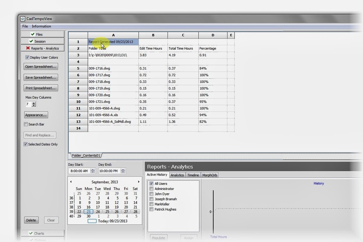
The CadTempo Timer Display


You will note that in this image the optional Task Timer and Activity Timers are enabled and displayed because "Extended Display" is selected as an option within the CadTempoView program allowing the user to view the current information. You can use this display to observe the timing functions of your CadTempo installation - see the help file for further instructions, this is found under: Contents>>CadTempo.exe>>Display Timer.

Let's begin by examining the information that is displayed in the lower section of the display.

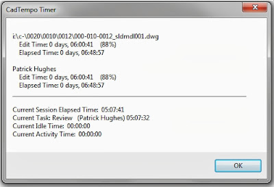
Current Session Elapsed Time:

Session Time

You might think of the Session Timer as a time punch clock that you punch in as you begin your day in the morning and punch out when your day is over. But there is a major difference, the CadTempo session timer is started automatically - there is no time clock to punch in or out of.

The CadTempo application is started automatically when the user logs onto the computer. When CadTempo detects that a monitored production application is started, the Session Timer is started and begins its tally. Any monitored production application will start the timer so if you have selected to monitor AutoCAD, Inventor, or Solidworks any of those programs will start the timer. The Session Time will continue to increment while any of the monitored programs remain open. Once all monitored production applications are closed the session time is ended and the results are written to the log. You may witness several session times being recorded throughout the day as you open and close your monitored production applications.

Current Task:

Task Time

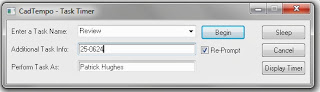
When enabled, the Task Timer will prompt the user for a task name based on the list within the CadTempoView Options settings window. If the "When Session Begins" check box has been checked the prompt will appear when a monitored application is started. If left un-checked the prompt will appear upon Windows start up. A user is presented with a prompt as shown:


The visibility of the "Display Timer" button is controlled by an option within the CadTempoView program.

The user may select a pre-defined task name using the drop-down combo box or may enter a custom name. When entering a custom name the custom name is remembered during the CadTempo program's life and will continue to appear in the list, but is not added to the persistent pre-defined list.

The user may enter additional information that is specific to the current task.

An alternate user name may be specified. This may be useful if you or a user is performing a task on another user's computer, however the currently logged on user name is also recorded.

By checking the "Re-Prompt" check box the task timer prompt will be re-issued when a session has been completed.

A user may save the current task at any time by clicking the "CadTempo - Task Timer" in the Windows Task bar and selecting the "Finish" button which becomes visible once a task is started. If Re-Prompt is checked the prompt immediately re-appears to allow beginning a new task.

When a Session is ended the Save Task prompt will appear. The user may save the current task or continue with the current task. If a user elects to continue the current task the user will be required to manually perform a save unless there a log-off (or Lock, etc.) occurs. CadTempo will then perform an automatic save.


Current Idle Time:

Idle Time

The Idle Time is based on a user's keystrokes and mouse movement or button click while a monitored production application is the active window. Each input resets the counter and the timer will increment only when there is no input. By itself, the display of the Idle Timer is intended for understanding the functioning of the related time recordings. Its effect on the other timers will be described in their respective explanations.

Current Activity Time:

Activity Time

The idea behind the Activity Timer is to provide the user with a means of capturing extended time that is spent away from the computer. Often, a user may be interrupted during working hours to attend to a related activity such as a meeting or to consult with other departments. Perhaps a user regularly leaves a CAD program and drawing open during lunch hour or a short personal time break.

The Activity Timer is connected to the Idle Timer. You, as the CAD manager control what is acceptable as a reasonable amount of user idle time. Many users will experience momentary interruptions throughout their day, whether it be a client phone call, a restroom break or a needed diversion such as a brief discussion with a co-worker. The default value for this idle time is set to 5 minutes but you can adjust that up or down to your liking in the CadTempoView program.

When a user becomes "idle" the idle timer will begin counting up to the idle limit that is set. Once the idle limit is reached the Activity Timer begins its count up to its limit. The default activity limit is set to 20 minutes and is adjustable. If a user returns to the computer while under the limit and continues work the Activity Timer is reset to zero and the cycle begins anew.

If the activity timer reaches its limit, a prompt is issued and will be visible when the user returns to the computer. In this way a user can account for his extended time away from the computer rather than relying upon his memory at the end of the day or week to enter into a manual time sheet.

Using the default values of 5 minutes for the idle timer and 20 minutes for the activity timer a user can account for 25 minute (and more) of "away" time.


Finally, let's take a look at the document and user timers that are displayed at the top.

Document and User Timers:

Elapsed Time

The elapsed time is the total amount of time a monitored document type is open and has keyboard and mouse focus. The document may be an AutoCAD drawing, a Revit file, Inventor file or any number of file types you designate and associated with a monitored production application. This value will continuously increment while a document is open. When a user switches to another monitored production application the timer will immediately switch over along with the user and begin (or continue) timing the now current document. Each document retains its own elapsed time as well as the user time of that document.

Multiple users that access the same document are recorded independently and the document time is the accumulated amount of all users.

Edit Time

The edit time is the amount of time a user maintains keyboard and mouse activity within a known document type of a monitored production application. The edit time is affected by the idle timer. If a user is momentarily interrupted, the idle time, up to its limit is considered to be valid editing time. In this way a user is not penalized (not that they should be in any event) for brief periods of inactivity. There are of course many reasonable causes for these periods of idle time.

The resulting difference between Elapsed Time and Edit Time can be used as an indication of efficiency or productivity.

In summary, there is much going on within the CadTempo program to monitor your user activites and to document the time involved in various tasks. It can take a while to understand exactly how CadTempo functions and my hope is that I've described them to your satisfaction.


Wednesday, July 24, 2013

CadTempo 6 Preview is released

Collect, Crunch, Convey, Challenge

CadTempo 6 Preview is released, better, stronger, faster.

 
Since its inception, CadTempo has kept the pulse of your CAD and engineering documents, 3D model creators, drafters and CAD users - perhaps like no other time tracking application available. Whether you use AutoCAD, Revit, Inventor, Solidworks or a multitude of CAD applications (and even non-CAD applications like Notepad, Excel or Word) CadTempo reports back the amount of hours it takes to create and maintain the drawings and supporting files that are the lifeblood of engineering departments.
 
Now, with CadTempo 6 we’re stepping up our game, so you can too. CadTempo will collect your time investment data, crunch the numbers into usable metrics, and convey the results in numerous charts, graphs, and spreadsheets. Now the challenge for improvement is on you and CadTempo 6 fosters that challenge in an exciting new approach - more on that in future articles.
 
Feast your eyes on these most significant additions in this new release:
 
Active History: Quick, easy chart and spreadsheet listing of most recently worked on files. A dynamic bar graph displays which files have the greatest amount of hours spent. Select a date range, click a button, and done. At the same time a spreadsheet is created listing the files and the amount of time each user spends on the drawings for each day in the selected date range. Click into the desired bar and the selected file will be automatically located in the spreadsheet view.


Analytics – Applications: Review overall active time spent in all of your applications, production applications and non-production. Each user can be segregated for review or you can examine any grouping of users. In addition to displaying the amount of active time in an application CadTempo gauges the amount of engagement a user is involved with each application. Dynamically sample by week, week to week, or even total hours year to date. Here is a sample bubble graph:


Analytics – Trend: The trend feature graphs the historical performance that is recorded above. Again each user can be segregated or a group can be examined. You can review all applications, production applications or non-production applications. This can be a very powerful indicator of the value of changes to your system, training, or a number of factors that affect your users motivation and productivity.


Analytics – Orb Trend: The “Orb Trend” is a device that graphs a user’s (or group of users) composite score of several metrics. The Orb can be viewed as a "vessel” that contains the collected metrics. An internal scoring mechanism measures several factors that are based on a user’s performance and displays the progress that is made over a period of time. Like the Trend graph this can be used to gauge the effectiveness of changes that are made to your system.


Timeline: The Timeline displays a graph of user’s work session over a period of time. By selecting the date range a chart is dynamically created that marks a users default expected work session hours and the actual session hours. A separate calendar allows you to record important benchmarks or milestones.


MorphOrb: An odd  name for sure, but it describes the concept behind this new release. The previously mentioned “Analytics-Orb Trend” encapsulates the data that CadTempo collects (the Orb) and presents a graphical overview of users performance metrics. Over time your Orb undergoes a metamorphosis, indicating the direction of a user or group of users productivity, efficiency, or engagement of work. The MorphOrb is intended as a means of comparative analysis among a large group of individuals and organizations that have an interest in determining their strengths or weaknesses based on community historical data. There is much more to this aspect of CadTempo that will be made available in the coming weeks so stay tuned.

To summarize, CadTempo 6 is the ideal tool to Collect, Crunch, and Convey your time data then Challenge you to reach greater productivity through increased motivation and work engagement.

Here is your first challenge: Beat my current score of 39.17


The current download copy of CadTempo 6 is in a state of preview. It is fully functional and is labeled as a preview before the official release.

For a limited time during the preview period you can take advantage of the previous release pricing. The CadTempo pricing and purchase web page include a comparison of present and future pricing.

You can download a fully functional copy of CadTempo here: http://www.cadtempo.com/


Tuesday, June 25, 2013

Why I Like Working With AutoCAD 3D Solid Models - Reason #1

After creating the model you can produce isometric images for catalogs and manuals like this in less than 10 minutes.

Wednesday, April 17, 2013

Monday, April 1, 2013

Engineered Design Solutions Announces Latest Technological Development to be Included in Upcoming CadTempo Release 6.0.

Engineered Design Solutions Announces Latest Technological Development to be Included in Upcoming CadTempo Release 6.0.

Patrick Hughes, owner of Engineered Design Solutions said on Monday he is very pleased that his team of advanced time analyticians recently discovered a means of bending the time-space continuum in a way never before thought to be possible, for that matter never before conceived. Hughes described how two years and one week and four days (+/- a few hours and a minute or two) from now the team will contact the late Albert Einstein (a somewhat well regarded theoretical physicist) via a tubular-parallel space tunnel and in a collaborative effort will return on this date to make history as has never been made before. To clarify, Hughes continued, "this has never, ever been done in the history of mankind, that is, we are saying our technology allows us to travel into the future and in the blink of an eye return to the exact original point in time and space (within a precision of a few hours and a couple of minutes...oh and one or two furlongs). We now have the ability to announce history before it is even made - we no longer need to wait for it to happen" This is being forecast to be a great time saver.

Hughes goes on, mumbling a quote from Winston Churchill: "The farther backward you can look, the farther forward you can see." It was this quote that inspired us to look into new ways of exploring the past and now allows us to make determinations of the present day which of course is the future of the past. It is truly incredible.

Technical details are sketchy at this moment but the attached rendering (see below) depicts the core instrument that plays an integral part of this discovery. CadTempo 6.0 allows the CAD time analyst to include in its time tracking, a user's childhood engagement with the widely popular Etch a Sketch CAD hardware. This backward look is as far back as we have been able to peer into the history of a CAD user, quipped Hughes, but it provides us with a glimpse of today. It makes no difference if the user's first experience with this CAD training device was 20 years ago or 40 years ago.


Asked why this news is being released at this late hour of the day Hughes responded: Today, April 1st is notoriously known as the day pranksters ply their trade with falsities and foolishness, we decided it was best to allow these events to take place and run their course before our proclamation of these glorious achievements. We felt it was so important to world at large that the gravity of our news had the opportunity to be taken in the light of seriousness and not overshadowed by the tricks.

Tuesday, March 12, 2013

CadTempo 6 - On The Horizon.

We have some exciting news in the making, we're not quite ready to release details but for now I can say that the upcoming release of CadTempo will be, uh... how shall I say this - I know, more engaging. Yep, that pretty well sums it up. CadTempo 6 is being designed to engage you in analysing your CAD work efforts in new ways that will help drive you and your team to new performance levels.

Here is a visual metaphor just to give you an idea about what's in store:


Along with the release of CadTempo 6, pricing is set to increase. I hope you see this post before the new pricing is in effect because those installations of CadTempo 5 that are purchased prior to the release of 6 will be upgraded at no cost. So visit www.cadtempo.com to download a copy now. You'll have plenty of time to give it a test run.