Wednesday, June 18, 2014
Saturday, March 8, 2014
Installing CadTempo For Multiple AutoCAD Users
I recently received an email from a potential CadTempo user with questions I thought might help others. He was interested in knowing how to go about setting up CadTempo for 20 AutoCAD users and 3 administrators (supervisory personnel). So here is an abbreviated set of instructions covering the most important installation points.
You will be installing CadTempo from each user's computer - the target machine(s), but you may find it easiest to first create a folder on a shared network drive. Copy (or best, download) the installer to that folder, and execute the network installer copy from the target machines. The example shown is a shared, mapped drive which resolves to a server name.
During installation you will be prompted to select the type of installation. Subsequent prompting will hinge upon your choice. If you are adding additional users un-check the "Initial Installation" checkbox.
Our next concern is the component installation. For the initial installation you will select "Full Installation" - this will install both the viewer and the logger (CadTempoView.exe and CadTempo.exe). To add an administrator select "Viewer Installation". If you are adding additional users to be monitored then select "Logger Installation". The Installer will display a message to you if an incorrect selection is made based on your installation type.
Most importantly is the location of the program files and the log files that CadTempo will create. Note that in this example the viewer application is showing the drive letter to the shared network folder and the Logger and Data folders display the server name. It is important when browsing for a location that you navigate to the location from the Network node of the selection dialog box. This will populate the field with the server name.
The folder selection options are dependent upon the components selected. This example is showing the Full Installation and therefore asks for all locations. When you perform a Viewer or Logger Installation only those selection options are presented, also you will be selecting the File rather than Folder. The Data Log File Location only appears for the Full Installation.
When you have completed the Setup you will be prompted to start the program(s). If you will be installing additional users it is best to postpone this final step until all users have had the software installed however, in order for monitoring and logging to begin, each user should log out then back in.
There are additional steps throughout the setup routine. You can view the full installation guide at this link: Multiple User Install Guide.pdf
Finally, keep in mind that CadTempo may not log the activities you are interested in immediately. You may wish to open the viewer program and make adjustments in the Options section. In particular the Applications and File Types tab. CadTempo also is dependent upon monitored file types and applications being opened and closed. If you find after some time goes by and no time values are being displayed it is most likely due to monitored programs continuing to run on the target machines.
You will be installing CadTempo from each user's computer - the target machine(s), but you may find it easiest to first create a folder on a shared network drive. Copy (or best, download) the installer to that folder, and execute the network installer copy from the target machines. The example shown is a shared, mapped drive which resolves to a server name.
 |
Shared Folder Example |
During installation you will be prompted to select the type of installation. Subsequent prompting will hinge upon your choice. If you are adding additional users un-check the "Initial Installation" checkbox.
 |
Installation Type Prompt |
Our next concern is the component installation. For the initial installation you will select "Full Installation" - this will install both the viewer and the logger (CadTempoView.exe and CadTempo.exe). To add an administrator select "Viewer Installation". If you are adding additional users to be monitored then select "Logger Installation". The Installer will display a message to you if an incorrect selection is made based on your installation type.
 |
Component Selection |
Most importantly is the location of the program files and the log files that CadTempo will create. Note that in this example the viewer application is showing the drive letter to the shared network folder and the Logger and Data folders display the server name. It is important when browsing for a location that you navigate to the location from the Network node of the selection dialog box. This will populate the field with the server name.
The folder selection options are dependent upon the components selected. This example is showing the Full Installation and therefore asks for all locations. When you perform a Viewer or Logger Installation only those selection options are presented, also you will be selecting the File rather than Folder. The Data Log File Location only appears for the Full Installation.
 |
CadTempo File Locations |
When you have completed the Setup you will be prompted to start the program(s). If you will be installing additional users it is best to postpone this final step until all users have had the software installed however, in order for monitoring and logging to begin, each user should log out then back in.
There are additional steps throughout the setup routine. You can view the full installation guide at this link: Multiple User Install Guide.pdf
Finally, keep in mind that CadTempo may not log the activities you are interested in immediately. You may wish to open the viewer program and make adjustments in the Options section. In particular the Applications and File Types tab. CadTempo also is dependent upon monitored file types and applications being opened and closed. If you find after some time goes by and no time values are being displayed it is most likely due to monitored programs continuing to run on the target machines.
Monday, September 23, 2013
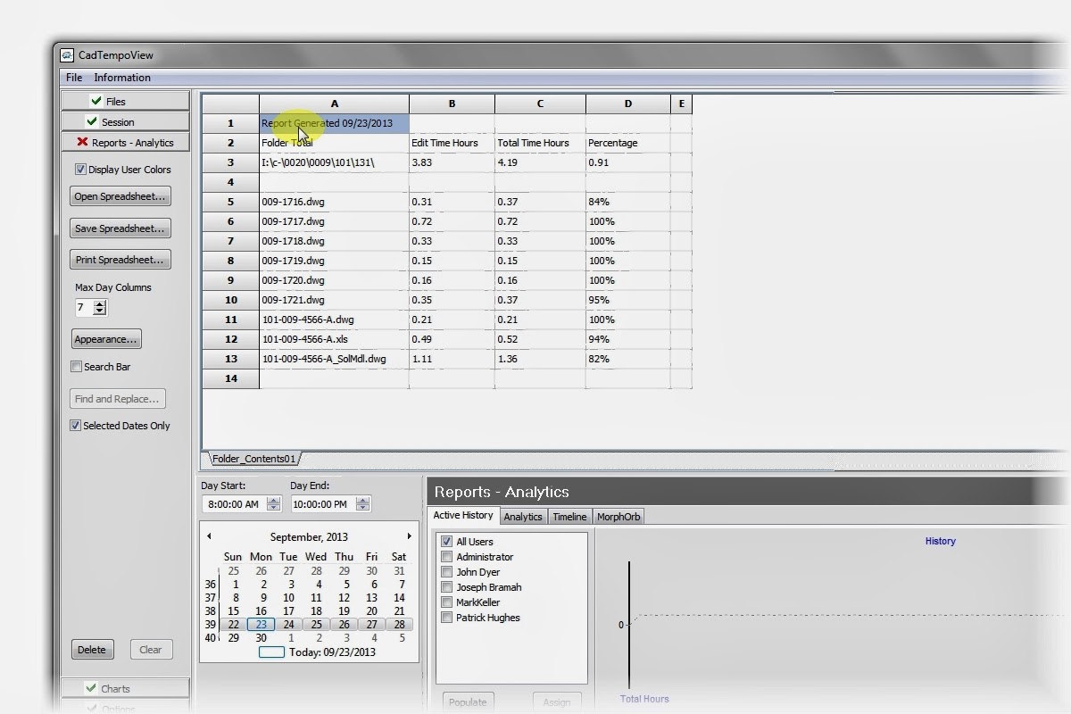
CadTempo - Creating Project Reports
Creating reports of your designers and drafters project time involvement is easy as pie. Here I'll show you the steps that are involved.
CadTempo is designed such that if your projects are broken into directories and sub-directories, project time totals can be summed easily by navigating to the desired folder and checking the files in that directory.
In the case I am demonstrating, I recently completed a small AutoCAD design and detail project of a tooling package. The project consisted of an AutoCAD assembly model constructed with 3D solids, the detailed AutoCAD drawings, an isometric drawing of the assembly and an Excel spreadsheet of the Bill of Material.
When you open the CadTempo viewer application it defaults to the file listing of the last folder you had open in the viewer. Navigate to the desired project folder and check the files in that directory. You can filter the displayed files by designating a filter mask then checking the Apply Filter box. Only visible and checked files will be included in the report.

Now, click the Folder Contents button.

Navigate to the Reports - Analytics page to view the report.
For a more detailed report return to the Files page and check the Include User Data box, then click the Folder Contents button once more.

Return to the Reports - Analytics page and you will see each user's time is added to a new spreadsheet page.

From the Reports - Analytics page you can print the report - you will need to print each spreadsheet page individually - or save the report to an Excel spreadsheet. Other save options include an html, rtf, and xml file types.
You can continue to add additional projects to the report - simply return to the Files page and navigate to other folders that you wish to include in your reports. Each time you click the Folder Contents button a new spreadsheet page is created.
So there you have it. Did I say it was easy as pie? Perhaps I understated the case.
Wednesday, August 21, 2013
The Return of Doctor Who and the CAD Manager
It seems like just yesterday we had taken a few trips back in time - well, to us time travelers it was yesterday! In real life though it’s been a little over a year. You see, the good Doctor was a bit miffed about the Cheetos dust that I had carelessly left on the controls of the TARDIS. It’s taken me this long to convince him I’ll take better care this time around. So let’s hop aboard and take a little jaunt back to the early days of CAD, say about the early to mid 80’s.
Keep in mind that I don’t have first hand knowledge of CAD systems of that time period but I do know how the available technology helped formulate how many work with CAD still today. It was a simpler time then, computers were of limited processing power, graphics capabilities were short on color options and memory was expensive. To utilize those machines it was very common to have simplified standards as well. A typical CAD drawing was made up of layer names that went like this: OBJ which would of course contain the line work of the parts being designed or detailed. Since you need to show features that are not visible there was a layer called HID or in some cases perhaps HID2 or some other designation to indicate a scale with a different linetype. Centerlines would be placed on yet another layer called CEN and again this would be of another color and linetype. DIM layers, while not so bright, held your dimensions and perhaps your notes. Last, and for the most part least, you might find a layer called PHAN containing phantom objects used for objects that were there, but weren’t.
All of the above seems rather reasonable - for 25 to 30 years ago. I often see this type of layering standard being promoted today, but I think there is a better way. One of the things I faced when I began doing contract design and drafting in 1991 was establishing a standard to work by. It was important to comply with the standards of my customers and I was happy to do so if it meant getting work. But there was a dilemma in that each of my customers had their own standards and seldom did one customer’s standards match another’s. Ultimately I decided it was more time efficient to not comply with any of my customer’s standards. Instead of switching from one standard to the next between jobs my efforts needed to be focused on creating my own standards, then employ the power of AutoCAD’s customization to convert my drawings to the individual customer standard.
You may not have a need to supply drawings of varying standards but my hope is you will find value in how I ended up organizing my layering conventions and what it meant to my work flow. Over the years I have evolved some of the details but since it is patterned in a way allowing for modification to various standards there was no reason I couldn’t adjust my standard as I go. So without further ado, let’s get to it.
My work consists of machine design and when you get right down to it machines are simply a compilation of many individual parts. The overarching concept that I started with was one of association. To put it simply, any line work associated with a part would exist on that part’s layer and each entity would have a color and linetype to indicate its feature (centerlines, hidden lines, etc.) The first order of layer management was to arrive at a naming convention. I Came up with the idea of using just three or four patterns and each pattern would be appended with a sequential numeric value. So for manufactured parts I started with DET0000 and the basic line work would be continuous, color black. Next, there are typically many purchased items involved and I wanted to segregate these items since they would not require detailing so, PUR0000 it was with line work of continuous, and by a stroke of genius the color was red. In cases where I needed a reference detail or assembly I used a REF0000 layer and in this case the layer linetype was set to phantom and the color was gray. Finally I needed a layer that would hold the contents of the part(s) that a machine was designed to work on, that would be PRT0000 layer, the linework would be phantom and the color would vary.
Creation of each layer is performed automatically with a combination of a custom toolbar and an AutoLISP program that looked up the next sequential number in a text file then incremented it. I created other programs that would allow me to isolate one or more layers and turn on or off layers by the pattern or by picking. Having linework associated with the layer meant that I would still see all centerlines or hidden lines with the particular layers when isolated. You can see what that means in these images.
Image of assembly model.

Isolating layer DET1316, DET1317, and REF0165 gives you everything you need to work on those details.

Isolating layer CEN doesn’t really offer you much value.

Another important aspect of how I’ve set up my layers is in the construction of the block libraries that I use. When a common part is needed whether it is a fastener or a commercial item my geometry is always placed on layer 0 and if centerlines or hidden lines are needed I will keep those entity types on layer 0 but created with the corresponding color and other properties. When inserted into the machine assembly or part detail they will be placed on the associated part layer and the line properties remain intact. The trick is if the item needs to be exploded I use an AutoLISP program that gathers the exploded entities and automatically changes the layer to that which the block was inserted into. Some of the more recent AutoCAD versions may have that capability out of the box.
The fly in the ointment are those files that you use from a third party source. Many vendors offer a vast array of product drawings at no cost and many items are available from the internet free for the taking. What a huge bonus in time savings. While these can save you lots of time in design you might consider an intermediate step before using them - spend a little time changing them over to your standard. That can save you some headaches down the road. And don’t forget to check dimensional accuracy.
Finally, I created much of my standards with automation in mind. When I began, long file names didn’t exist - we were limited to the old DOS 8 characters with an extension. The use of shortened layer names allowed me to create macros and AutoLISP programs that once a layout was completed each detail part file was created with very little manual effort. For now I’m sticking with the short file names because I find typinginreallylongfilenames.dwg names somewhat cumbersome, but I can see where a well laid out convention could work.
Well even though the use of the TARDIS means we can arrive back at any time we desire (so we’re not going to be late) it may be prudent for us to take our leave now. I don’t want to run the risk of a sudden Dalek appearance potentially causing damage to the TARDIS. Happy layering.
Patrick Hughes is a machine designer in Rockford, Illinois, USA, and owner of Engineered Design Solutions, a provider of machine design contracting services. He has developed numerous AutoLISP and other software solutions to automate his workflow and increase his productivity throughout his years in business. Patrick developed the CadTempo time tracking program to aid his quest for further refinement of his processes, and invites you to investigate how it may help your organization. Find out more by visiting the CadTempo website at www.cadtempo.com. Reprinted with permission from Autodesk User Group International (AUGI), AUGI Hotnews, April 2013
Subscribe to:
Posts (Atom)


